Deterministic processing path
Critical tasks receive clear priorities and cycles without dependence on cloud connectivity.
TECHNOLOGY 02 / ALERT LATENCY
Meaningful latency is measured from a sensor observing change to the HMI, lamp or buzzer issuing an alert—not merely the processor execution time.
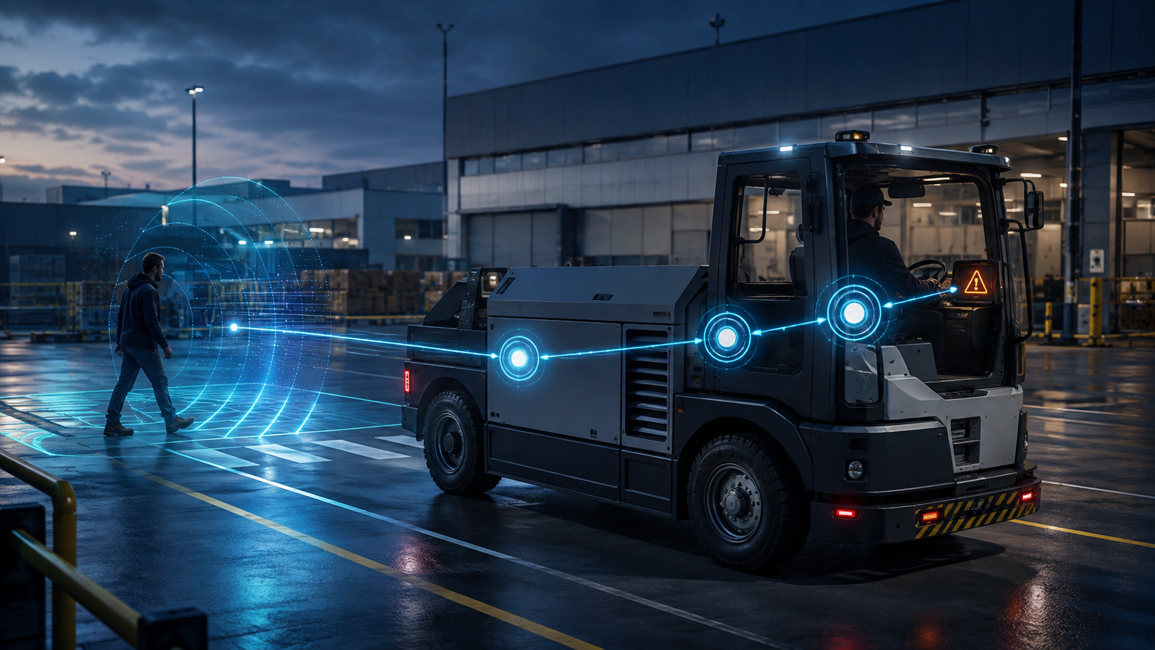
NORTHAR structures the chain into sensor sampling, transfer, fusion, hazard evaluation and alert output. Sub-100 ms is an engineering target for a suitable configuration; final performance depends on the sensor, bus load, object count and filtering logic.
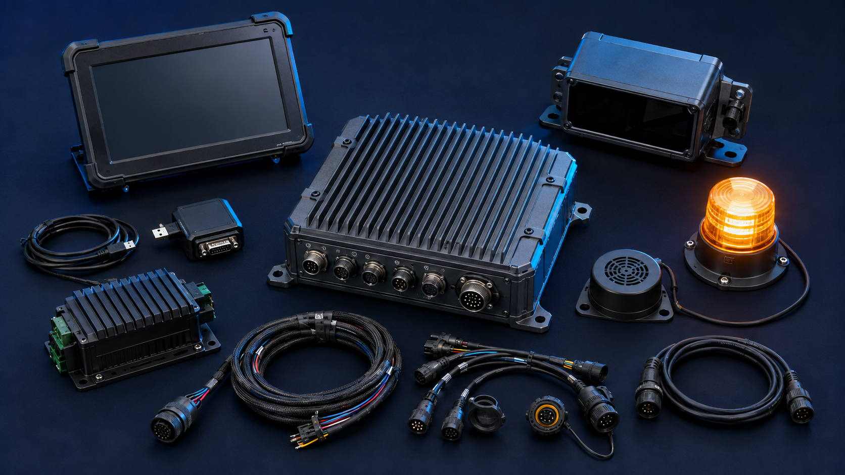
REFERENCE HARDWARE KIT
The kit is configured around the vehicle, voltage, warning zones and available interfaces. The image represents an OEM-neutral design; the final model and appearance may change after manufacturer selection.
DESIGN PRINCIPLES
Presented at architecture level; the final commercial configuration depends on the vehicle survey and safety requirements.
Critical tasks receive clear priorities and cycles without dependence on cloud connectivity.
Attention, warning and danger zones reduce unnecessarily aggressive early alerts.
Validation includes sensing, transport, processing and the physical alert device.
Fast response and independence from an external network.
Finite compute resources and a need for optimized real-time software.
Core architecture for safety alerts on the vehicle.
Large-scale aggregation and centralized model updates.
Latency and availability depend on connectivity; unsuitable as the primary warning path.
Used for reporting and fleet analytics, not as a replacement for local warning.
Robust, prioritized and widely adopted vehicle communication.
Lower bandwidth than Ethernet and requires bus-load management.
Suitable for compact sensor, vehicle-state and warning messages.
High bandwidth for cameras, LiDAR and raw data.
Higher network cost and integration complexity.
Upgrade path for data-heavy sensing configurations.
UPGRADEABLE ARCHITECTURE
The roadmap is managed by hardware, software and per-vehicle configuration versions.
Keep the warning path local, limit background work and timestamp events.
Increase payload where supported while monitoring bus load and response time.
Add a high-speed path for cameras, LiDAR or AI processors.
Record processing cycles, communication faults and threshold overruns.
TECHNICAL REFERENCES
Share the vehicle model, dimensions, speed and blind zones. NORTHAR will propose a configuration and validation plan.
Talk to an engineer →